1. The
directed rate of flow of electric charge through any cross-section of a
conductor is known as electric current.
If ∆Q charge flows in time ∆t, then current at any time t is

If ∆Q charge flows in time ∆t, then current at any time t is

NOTE: Current is a scalar quantity.
I is in the direction of flow of positive charge and opposite to the direction of flow of negative charge.
SI unit of current is ampere and is represented by A.

I is in the direction of flow of positive charge and opposite to the direction of flow of negative charge.
SI unit of current is ampere and is represented by A.

2. The current density at a point in a conductor
is the ratio of the current at that point in the conductor to the area of
cross-section of the conductor at that point provided the area is held normal
to the direction of flow of current.

NOTE: Current density is a vector quantity.
3. Flow of Electric Charge in Metallic Conductors Among the solids, all metals are good conductors of electricity. The cause of conductance is free electrons.
In Case of a Solid Conductor (i.e. Cu, Fe, Ag, etc) atoms are tightly bound to each other. There are large number of free electrons in them.
In Case of a Liquid Conductor Like electrolytic solution, there are
positive and negative charged ions which can move on applying electric field.
4. Drift Velocity It is defined as the average velocity with which the free electrons move towards the positive end of a conductor under the influence of an external electric field applied.

5. Electric current in terms of drift velocity


6.
Current density at
any point of conductor,
j = nevd
where, j is a vector quantity.
j = nevd
where, j is a vector quantity.
7. Mobility The ratio of drift velocity of electrons and the applied electric field is known as mobility.

8.
Ohm’s Law At constant
temperature, the potential difference V across the ends of a given metallic
wire (conductor) in an circuit (electric) is directly proportional to the
current flowing through it.

The
variation of current w.r.t. applied potential difference is shown with the help
of following graph.
V = IR
where, R = resistance of conductor
No effect of V and I on R because as V increase, I increase but R remains the same.
V = IR
where, R = resistance of conductor
No effect of V and I on R because as V increase, I increase but R remains the same.
9. Resistance of a Conductor Mathematically, it is the ratio of potential difference applied across the ends of conductor to the current flowing through it.
=> R = V/I
SI unit is ohm (Ω).
Resistance can also be written as,
R =ρ L/A
where, L = length of the conductor, A = area of cross-section and ρ = constant, known as resistivity of the material. It depends upon nature of the material.
10. Relationship between resistivity and relaxation time

12.
Temperature Coefficient of
resistance is given by

14. Superconductivity The resistivity of certain metal or alloy drops to zero when they are cooled below a certain temperature is called superconductivity. It was observed by Prof. Kamerlingh in 1911.
15. Relationship between current density (j), electric field (E) and conductivity (σ) is
j = σ E
16. Some Important Units

18. Color Code of Resistance The color code on carbon resistor remains in the form of coaxial rings.
The first band represents the first significant figure, second band represents second significant figure and third band represents multiplier (i.e. power of ten). The fourth band represents tolerance.

19.
Combinations of Resistance There
are two types of resistance combinations.
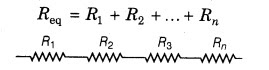
(i) Series Combination In this combination, different resistances are connected end to end.
Equivalent resistance can be obtained as the formula,

13.
Conductivity It
is defined as the reciprocal of resistivity of a conductor.
It is expressed as, σ = 1/ρ
SI unit is mho per meter (Ω-1/ m).
It is expressed as, σ = 1/ρ
SI unit is mho per meter (Ω-1/ m).
14. Superconductivity The resistivity of certain metal or alloy drops to zero when they are cooled below a certain temperature is called superconductivity. It was observed by Prof. Kamerlingh in 1911.
15. Relationship between current density (j), electric field (E) and conductivity (σ) is
j = σ E
16. Some Important Units

17. If a conductor is stretched or compresses to n
times of original length, then
l’ = nl => R’ = n2R
where, R’ = new resistance and R = original resistance.
l’ = nl => R’ = n2R
where, R’ = new resistance and R = original resistance.
18. Color Code of Resistance The color code on carbon resistor remains in the form of coaxial rings.
The first band represents the first significant figure, second band represents second significant figure and third band represents multiplier (i.e. power of ten). The fourth band represents tolerance.

(i) Series Combination In this combination, different resistances are connected end to end.
Equivalent resistance can be obtained as the formula,

19.
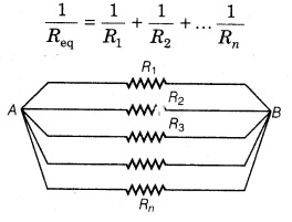
Combinations of Resistance There
are two types of resistance combinations.
(i) Series Combination In this combination, different resistances are connected end to end.
Equivalent resistance can be obtained as the formula,
(i) Series Combination In this combination, different resistances are connected end to end.
Equivalent resistance can be obtained as the formula,

NOTE: The total resistance in parallel combination is less than the least resistance of the circuit.
20. If n identical resistors each of resistance r are connected in
(i) series combination, Req = nr
(ii) parallel combination, Req = r/n